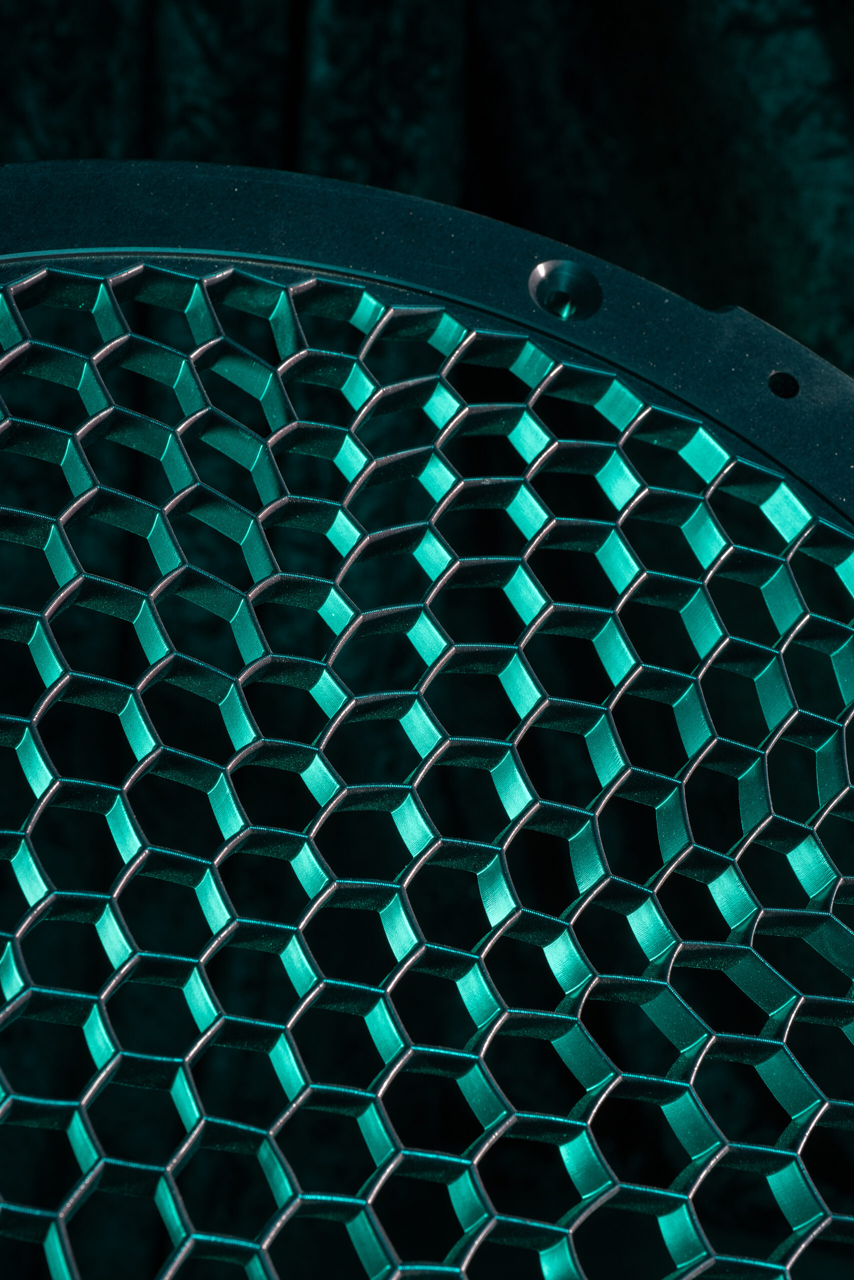
What are swirl screens?
Swirl-screens are custom-designed devices that shape the airflow entering a turbomachinery test rig. By precisely tailoring stagnation pressure, swirl angle, pitch angle, and turbulence intensity, they allow engineers to reproduce the complex, non-uniform flows that real engines experience.
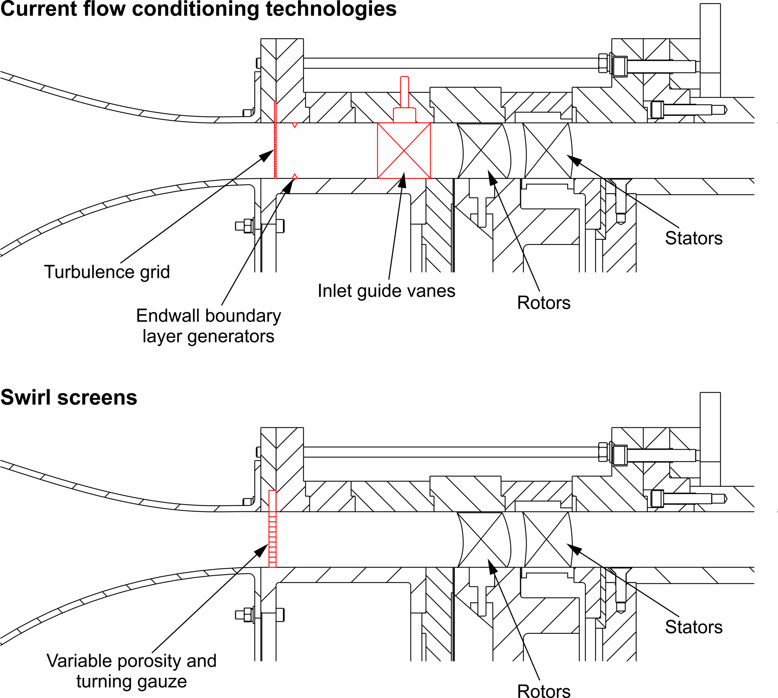
Unlike traditional grids or vanes, swirl-screens combine pressure and swirl distortion in a single, compact, low-cost component. This makes them invaluable tools for studying fan–distortion interaction in boundary layer ingestion (BLI) propulsion, crosswind conditions, and high bypass ratio turbofans. They can also be used to replicate the flow in the middle of an engine, simulating the flowfield downstream of struts, ducts, combustors or the cumilative effect of many upstream blade rows.
Technical Approach
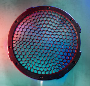
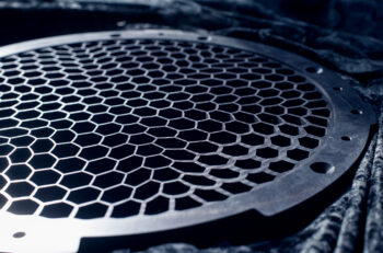
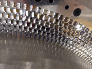
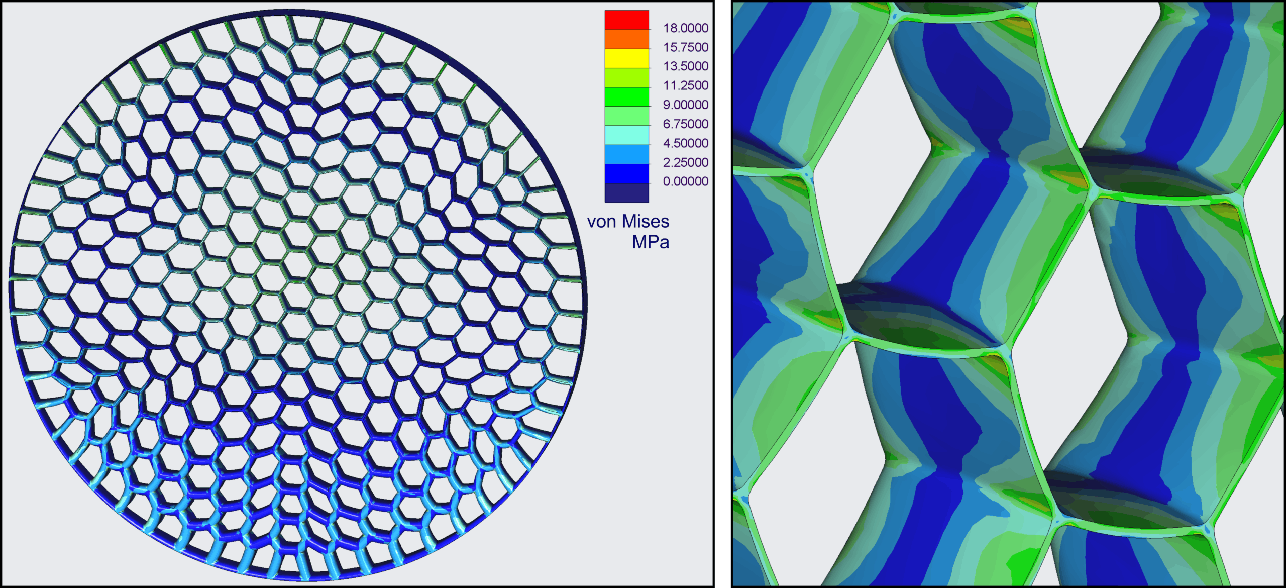
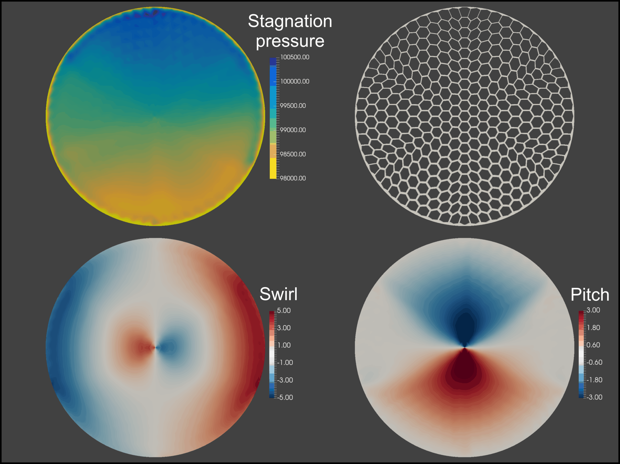
Swirl-screens consist of thousands of finely designed radial and circumferential blades. By varying their thickness, porosity, and camber, they control:
-
Stagnation pressure distribution
-
Swirl angle in tangential direction
-
Pitch angle in radial direction
-
Turbulence intensity
This level of control allows researchers to decouple different distortion effects—critical for fan design, stall studies, and CFD validation.
Further technical information available in two open-access published articles:
https://doi.org/10.1007/s00348-019-2682-9
https://doi.org/10.1007/s00348-021-03290-9
Case Studies
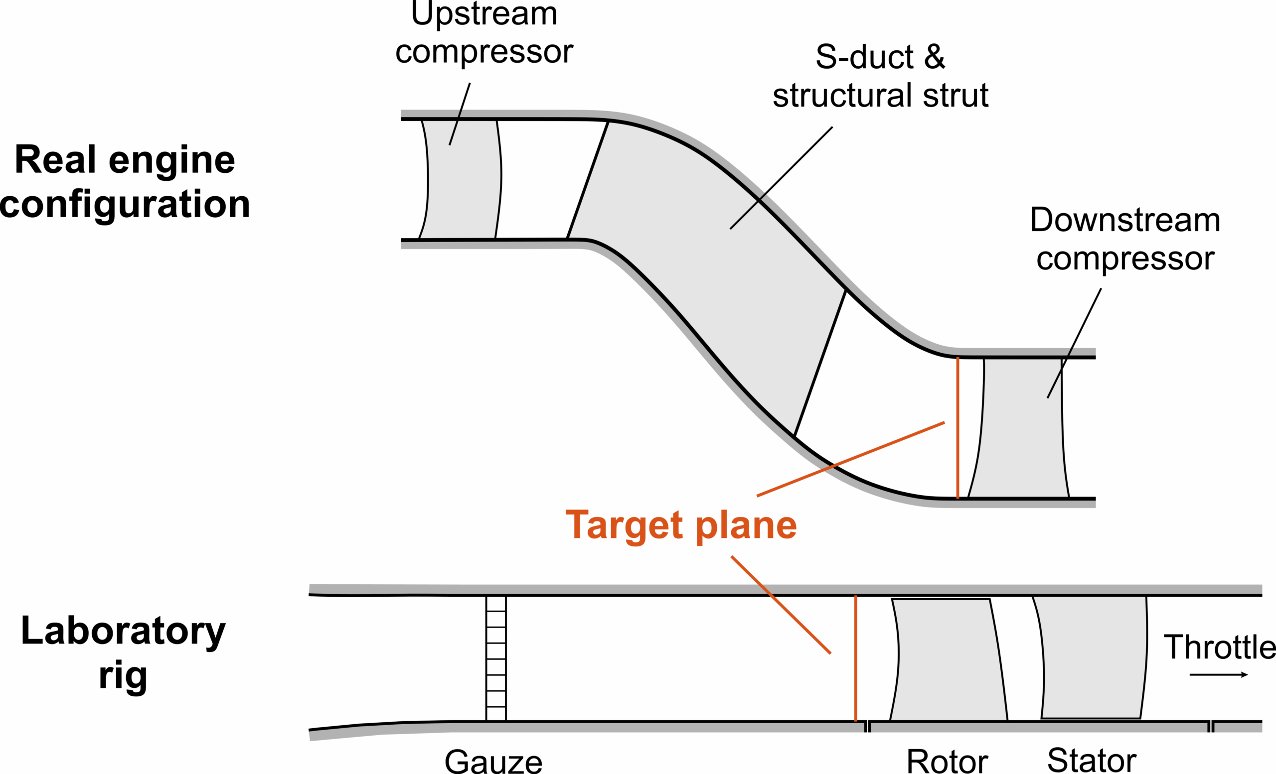
Gibbons Compressor:
Embedded single stage experiment
Goal:
Improve compressor efficiency and stability with improved endwall flow mechanism understanding.
Challenge:
Rear-stage compressors in industrial gas turbines experience complex inlet pressure profiles that are hard to reproduce in a single-stage test rig.
Solution:
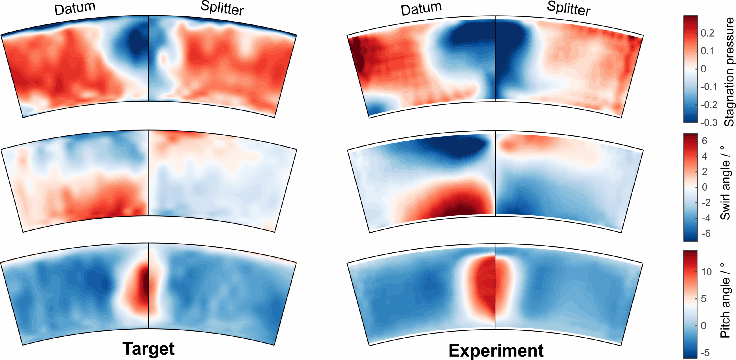
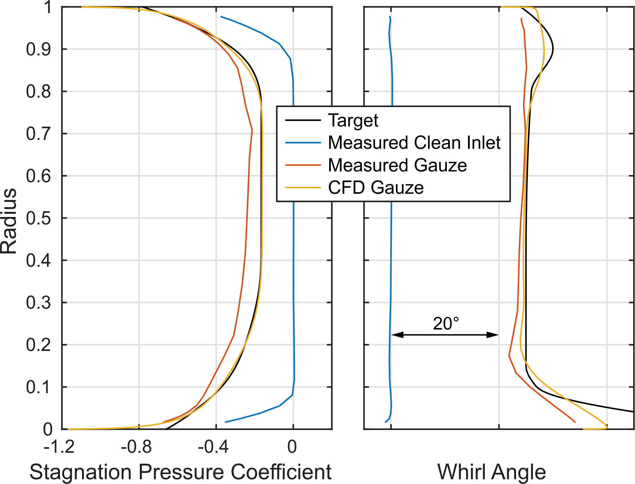
A swirl-screen designed as a complete flow-conditioning gauze was installed in the Gibbons Compressor rig at the Whittle Laboratory.
It precisely shaped the stagnation pressure and flow angle profile entering the rotor allowing demonstration of new designs and in-service issues to be determined.
https://doi.org/10.1115/1.4064317
https://doi.org/10.1115/GT2020-14906
https://doi.org/10.1115/1.4050596
Outcome:
-
Recreated realistic embedded-compressor inlet profiles in a compact rig.
-
Validated CFD-based tip-treatment designs experimentally.
-
Demonstrated how swirl-screens can support both research and industrial development.
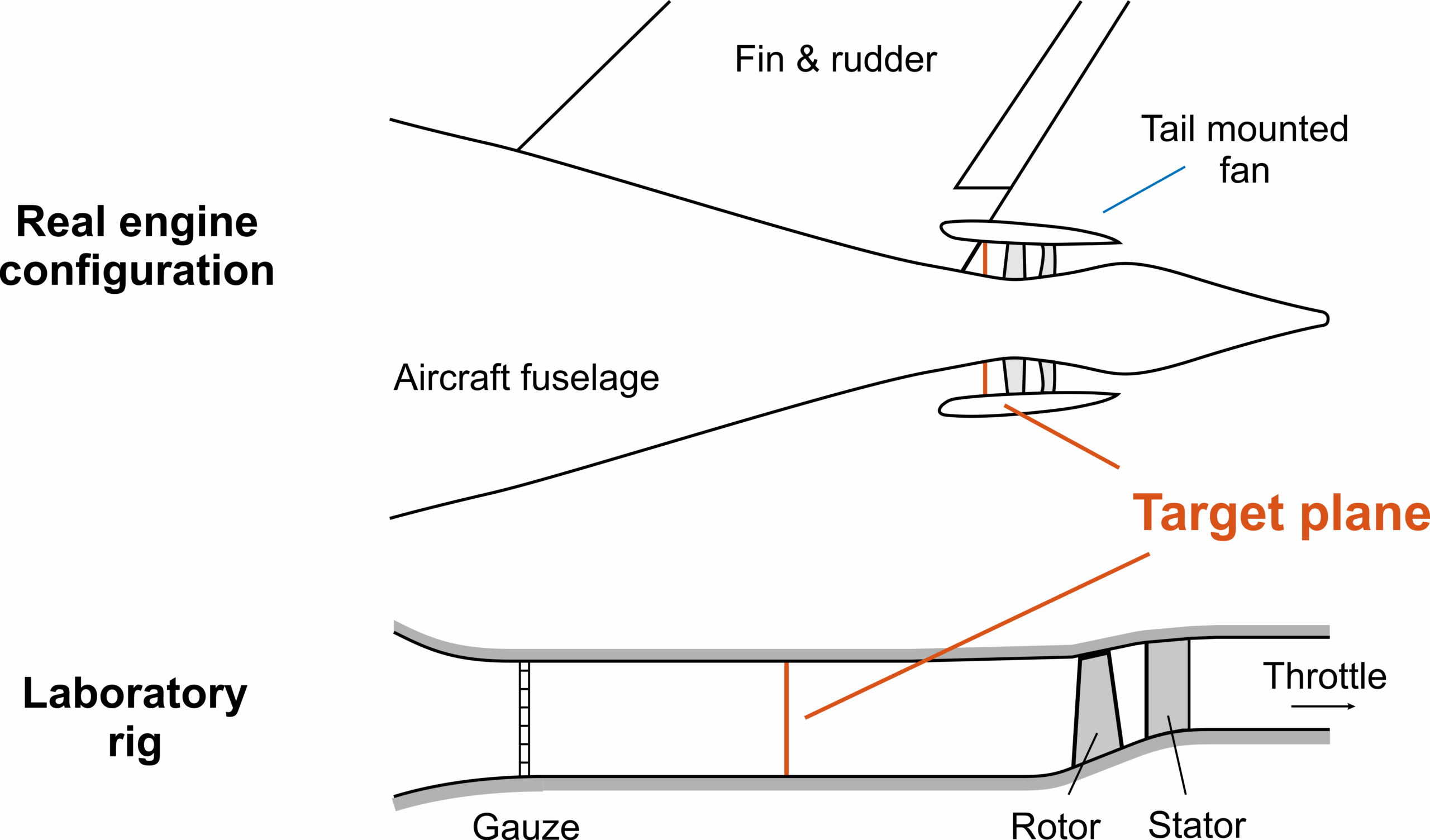
Boundary-Layer Ingesting (BLI) Fan:
Fan performance in distortion experiment
Goal:
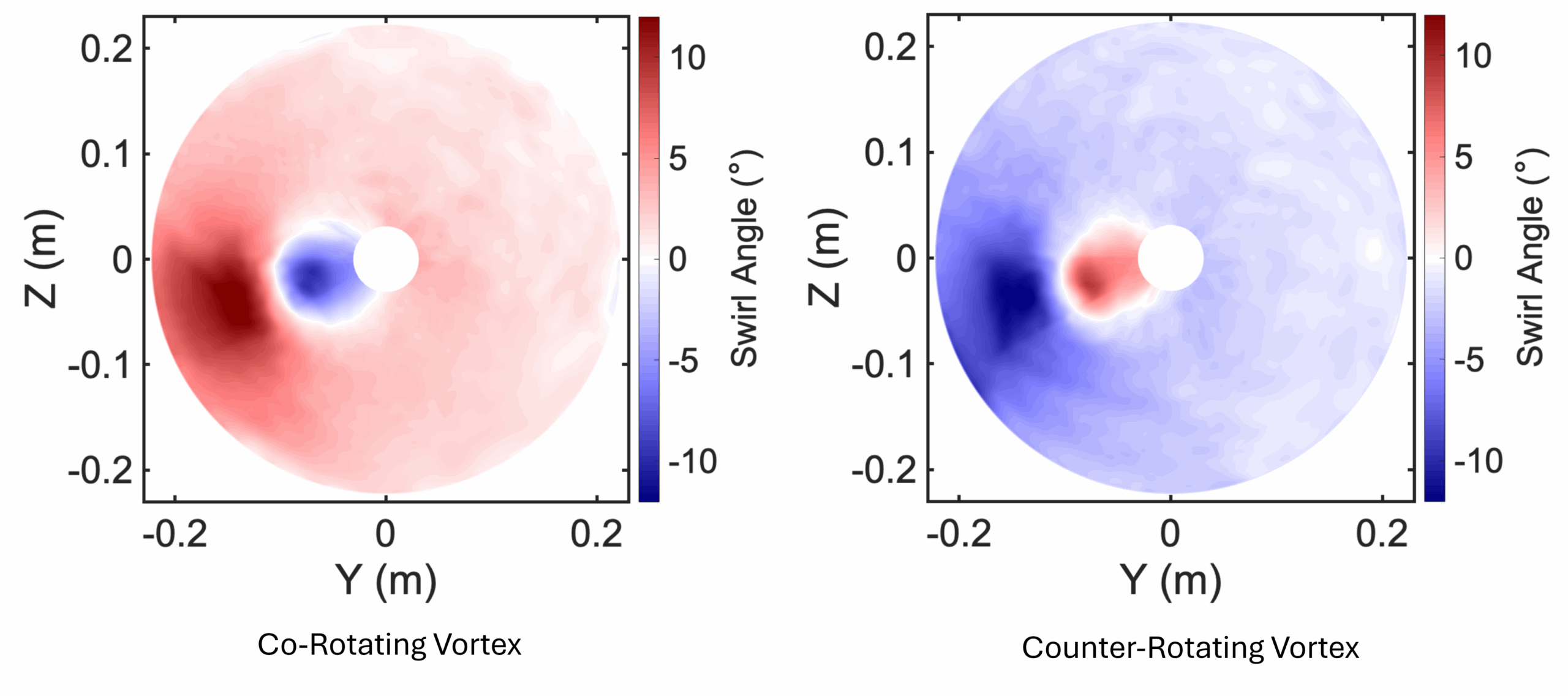
Understand how tightly-wound vortices affect fan loading, pressure rise, and stability.
Challenge:
BLI fans ingest slower boundary-layer air from the fuselage, leading to strong co- and counter-rotating swirl patterns that are difficult to control in tests.
Solution:
Two custom 3D-printed swirl-screens generated equal-strength, opposite-direction vortices at the fan face.
High-resolution traverses and unsteady casing-pressure sensors captured how these vortices propagated through the fan. (Pilav, 2025)
Outcome:
-
Counter-rotating swirl increased fan loading by 3.7%; co-rotating swirl reduced it.
-
Both cases reduced efficiency by only ~1%, proving the distortion was mainly aerodynamic rather than dissipative.
-
Revealed distinct stall-cell patterns triggered by swirl direction.
Technical Requirements
Needed from you:
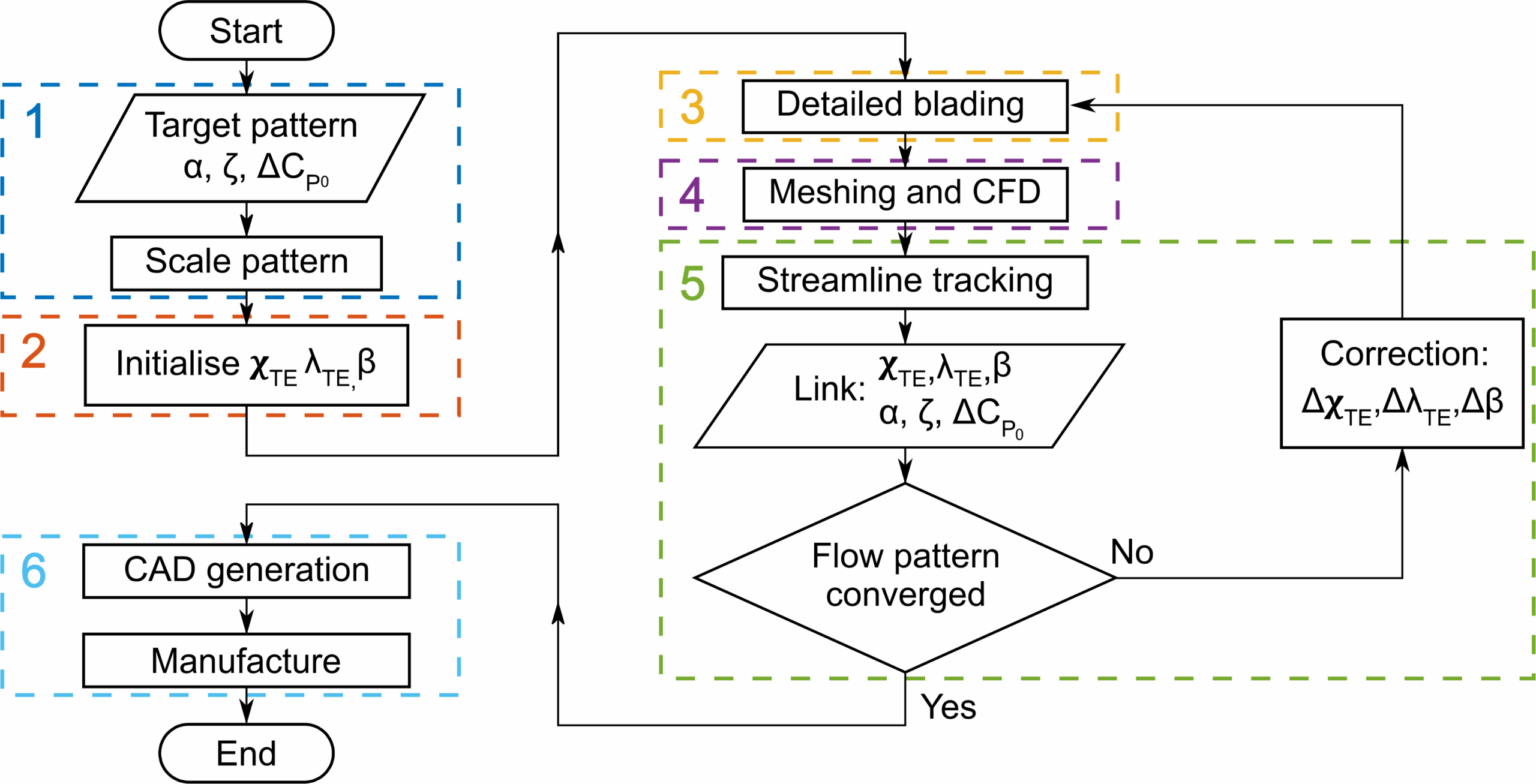
- Description of the flowfield you want at the target plane of the experiment, from CFD or another experiment.
- Expected flow conditions upstream of the swirl screen location, if available.
- Hub, casing and other geometry if interacting with the region of the swirl screen.
What we will do:
- Iteratively run CFD to design the swirl screen tailored for your experimental setup.
- Perform static and modal analysis on the screen with expected loads.
- Provide you with 3D models of the screen if you want to print it yourself.
- Machine a metallic design on our five-axis machines and ship it to you ready for your high-speed experiment.
Design limits:
Max Mach Number: 0.8
Max Radial Pitch Angle: 85°
Max Tangential Swirl Angle: 45°
Please contact us at swirl-screens@eng.cam.ac.uk if you have any questions.